.avif)

A Guide to CAD and CAM
From the day that man started drawing in the sand and on the walls of caves, humans have been communicating with each other in ever more sophisticated ways. Fast forward a few millennia and humans had moved on to drafting in pen and ink.
With the advent of computing, technologists saw the benefits of assisting this process via a new form of processing power. Input devices were soon developed, such as Sketchpad, which improved accuracy and the ability to modify 2D drawings. No longer was the eraser required if you needed to change a dimension or copy a feature around an array.
And so computer-aided design (CAD) was born.
Around 25 years ago CAD went 3D and the software has evolved from this point to be used for a whole range of applications (it was used to develop Concord in the 60's using wire-frames, due to the limitations of computation power).
From here CAD evolved into what students of product design nowadays would be more familiar with. It is now commonly used across a number of design disciplines including engineering design, parametric modelling and surface modelling.
Let’s take a look at some of these concepts.
What are Surface Models?
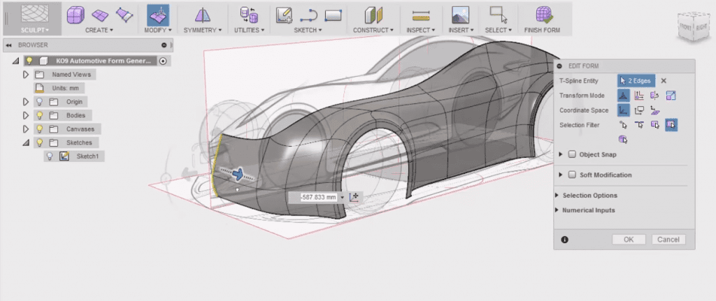
Surface models are used in CGI animation and visualisation. In product development, they are used in cases where we need excellent and subtle control of guess what - surfaces. Think Car body panels or detail areas of aesthetic importance. Surface models are not “watertight” but that does not matter if you're rendering a movie or visualising.
What are Solid Models?
Solid models are useful as they behave as virtually real “watertight models” so you can add or subtract from them as you would in a machine shop. As a solid body and assembly of solid bodies, these can be said to have mass and materials characteristics for you to quickly assess things like centre of mass, structural testing known as FEA (Finite Element Analysis).
What are Parametric Models?
Parametric modelling is essentially the process of building a 3D model by a series of instructions or “parameters”. Most often this is used to build “ solid models” not surface models. But in some cases both are possible. Parametric modelling took off in the 90s and now all product design development is designed using this type of CAD software.
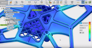
What is Generative Design?
Great CAD software can be a bit of a chocolate teapot without an efficient interface between user and machine. Input devices are therefore fundamental to your efficiency when using CAD. There are a number of solutions out there to this problem, but for us the 3DConnexion Space Pilot device we could not immerse ourselves freely in CAD without this awesome 3D mouse any more than a journalist could type without a keyboard
What is CAM?
CAM stands for Computer Assisted Manufacture. In modern terms, we design in a “virtually real” place. We get lost for hours in that virtual sculpture studio or workbench. When we want to bring that back in the real world we require an output into the physical. Just as you might print a document to proofread. You might want to 3D print your concept sketch model, to test its basic attributes, size and shape etc. This is the essence of CAM. You can’t really use CAM without feeding it CAD first.
CAM comes in many forms. For the most part injection, moulded products will be first developed in CAD. Then Tools CAM robots will essentially mill steel from Billet to create the injection mould tool impressions.
The negative of the CAD model in steel it that it permits injection moulding of the cavities. CAM is literally a robotised manufacture process. Other examples of CAM would be 2D CNC (Computer Numeric Control). This is used in making furniture for example and Open Desk use of CNC to revolutionise CAD in Furniture.
CAM really can include any robotised system, so could even include car plant robotics where forming and welding are used to construct car bodies, through to additive manufacturing jobs like 3D printing.
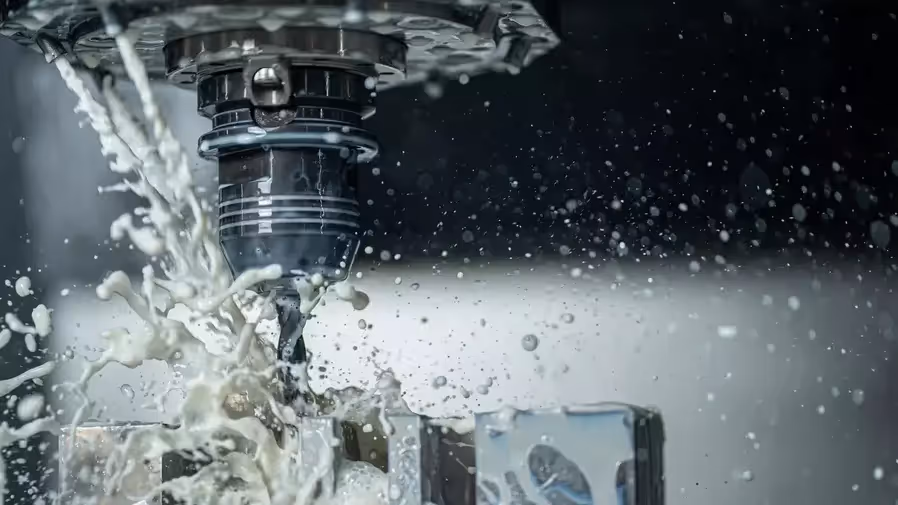
Through to 5 Axis CNC in this amazing example of just how sophisticated the technology has become
What are the Benefits and Drawbacks?
There are many benefits to using CAD/CAM as integrated processes, as opposed to separate entities. Manufacturers are now trying to create “better products faster, at lower cost, and with less waste”
Here are just some of the benefits:
- Efficient - It can speed up design time and manufacture as a 3D model can be used to create drawings and visualisations. In the case of CAD/CAM, the file can be directly used in the manufacturing processes.
- Scalable - It can be used for quick concept prototyping, one-off runs to batch or mass production
- Adaptable - Design and production runs can be easily updated or modified to suit consumer needs.
- Accuracy - Processes can reduce waste and energy in production due to greater efficiency, more accurate tooling and less chance of human error. This will improve control of capabilities within the program.
Some of the drawbacks of CAD / CAM include:
- Software is a tool - Like any tool, CAD/CAM has limitations. Software's are improving all the time. We like Fusion 360 as it blends many things into one package. Traditionally you might have worked with Rhino3D and then imported. Step files into a Solid Modeller. Fusion does much of this inside one program. Freedom of a surfacer and the benefits of a Solid modeller without the corruption and lack of parametric tree which occurred on a blank import of a surface model. Modern cloud software integrated more freedom for design intent to be carried through your workflow. Older systems got in the way of what you had in your mind's eye and what the software permitted. Again using Clay you are free to sculpt.
- Computer Says No! Software Crashes. Fillets fail to compute. Shells fail to compute. You might have achieved the shape you really want, but now you're looking at limitations of the software, maybe it does not shell apart at the desired thickness. Maybe a part fails to Boolean, over time you develop workarounds for this bugs. If you have to debug a large assembly for issues, you might waste time with Tech support looking at what's going wrong. This is rare but it can happen to the best of us.
What is the future of CAD?
With an ever-changing digital landscape, the potential for CAD/CAM processes is endless. Here are just a couple of potential future applications:
- Replacing bodily parts - Currently, CAD/CAM is able to manufacture prosthetic 3D printed limbs, which if successful, could be used for more medical purposes in the future.
- Integrated Realisation - Whilst renders have a purpose to communicate how aspects such as colour, material, and finish, they don’t give an actual representation of the functionality of the model. New technology will allow more understanding of features such as fluid dynamic analysis to improve functionality, this will save money and waste.
We provide businesses with product design consultancy, industrial design, prototype design & related services.